Definitions
Photomask (Master/Mask) – In its simplest form, carries the pattern to be printed. The layout of this pattern is generated by transforming the drawing with the help of CAD tools into geometrical shapes. A master/mask is a thin coating of masking material supported by a thicker substrate. The masking material blocks light to varying degrees and can be patterned with a custom design. The pattern is used to modulate light and transfer the pattern through the process of photolithography which is the fundamental process used to build encoder scales and discs.
A photomask is glass substrate, coated with an opaque film into which is etched the design of the device being manufactured.
The photomask plays a critical role in the lithography process used by us for the manufacture of encoder scales, discs or other products. A photomask consists of a fused silica (QZ) or glass (SL) substrate coated with an opaque film, into which an accurate replication of the device designer’s pattern is etched. In addition to a high degree of pattern fidelity, the photomask also has to meet our expectations for line width, critical dimension (CD) control, pattern placement (registration), and defectivity control. The terms “masters”, and “copy masks” are usually used to refer to 1X photomasks, while the term “reticles” refers to 2X and 4X stepper photomasks.
Glass Photomask Polarity
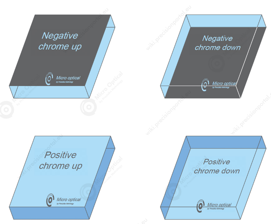
Masks are normally referred to as Clearfield (positive) & Darkfield (negative)
Positive means that the data you have drawn in CAD will be Chrome on the mask, with the background (the field) being clear glass.
Negative is the opposite of this, where the items drawn on CAD will be clear and the background will be chrome.
We also need to know which way round the mask has been designed on your screen. The easiest way to select this is to add some reference text (anything you like) to the design somewhere – maybe in the corner – and then specify if the text needs to be right reading or wrong reading.
Our processes and lithography tools are very different and uses two types of photo masks:
- The scale factor (2X to 4X reduction ratios for projection steppers)
- 1X Masters to substrate printing proximity (full-contact for scanners)
Copy Masks (Working Master)
When hard-contact printing used to transfer the design to their substrates, the photomask can quickly deteriorate due to mechanical damage. When the feature size and specifications allow, the most cost-effective solution can be to use a copy photomask made from a “master” or “sub-master”, which we retain for making additional copies as required. Copy masks are usually made on soda-lime (SL) glass substrates.
Reticles
When an optical projection stepper used with a reduction ratio of 4:1, the photomasks used in these systems are usually called “reticles”. This system use single wavelength from i-line (365nm). Reduction stepper reticles typically support the most stringent lithography requirements. Typical projection stepper used to repeat small imaging pattern or multiplicate with defined step. High resolution reticles are typically made on QZ substrates.
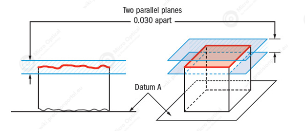
Flatness
Flatness – Glass surface flatness is the measure of how flat a surface is; this test is critical for good quality encoder scales and discs. The surface flatness measurement accounts for surface deviations such as ripples, bows, and other imperfections, which are measured in waves — the multiple of the wavelength from the reference surface. In this case, the higher the digit, the more precise the product.
The flatness tolerance references two parallel planes (parallel to the surface that it is called out on) that define a zone where the entire reference surface must lie. Flatness tolerance is always less than the dimensional tolerance associated with it.
Two Sets of Parallel Planes where the entire referenced surface must lie.

(Source: https://www.gdandtbasics.com/flatness)
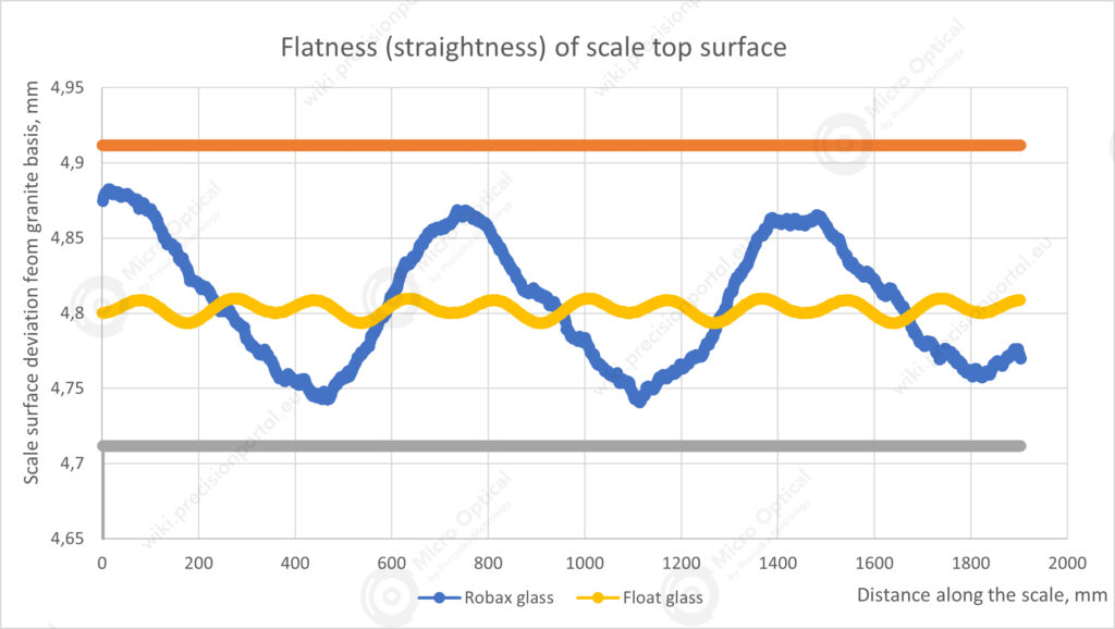
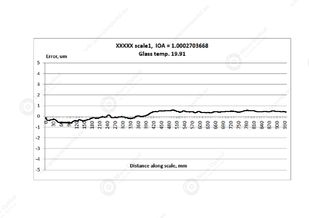
Linear scale, made from Robax glass is placed on granite base and sucked by vacuum. Granite base straightness is 4 microns. Scales in the graph are measured by “on fly” mode, every one millimetre.
Flatness of the disc
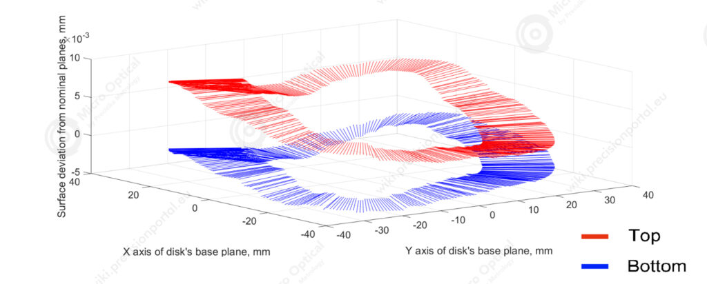
Measurement starts, when optical flat is placed on rotating table, three spheres supports. Supports are aligned in one plane, when table is rotating. After that, glass blank is placed on supports, and both surfaces are measured simultaneously, every one degree, while it’s rotating.
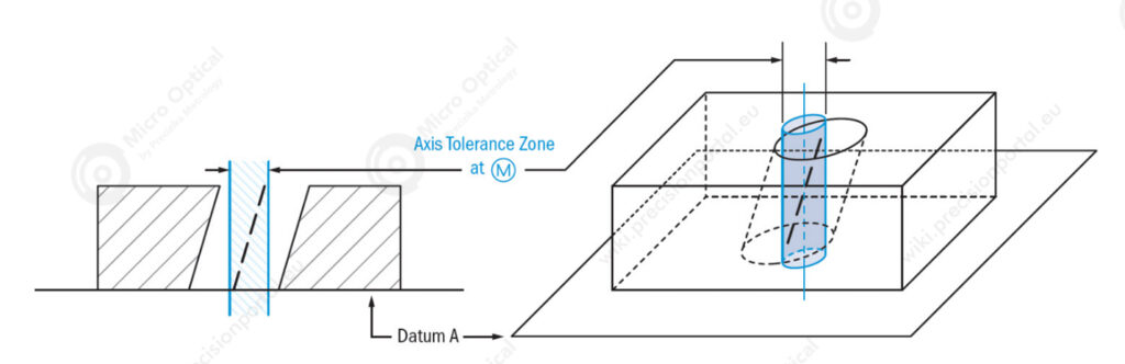
Axis Parallelism
Axis Parallelism is a tolerance that controls how parallel a specific parts central axis needs to be to a datum plane or axis. The axis form is controlled by a cylinder around a theoretical perfectly parallel axis.
A cylinder surrounding a referenced theoretical axis which is directly perpendicular to the datum feature. The tolerance zone is the diameter of this symbol in which the central axis of the measured feature must lie.
Parallelism describes how parallel two surfaces are with respect to each other. It is useful in specifying components such as windows and polarizers where parallel surfaces are ideal for system performance because they minimize distortion that can otherwise degrade image or light quality. Typical tolerances range from 5 arcminutes down to a few arcseconds.
(Source https://www.gdandtbasics.com/perpendicularity)
Disc Blanks Manufacturing
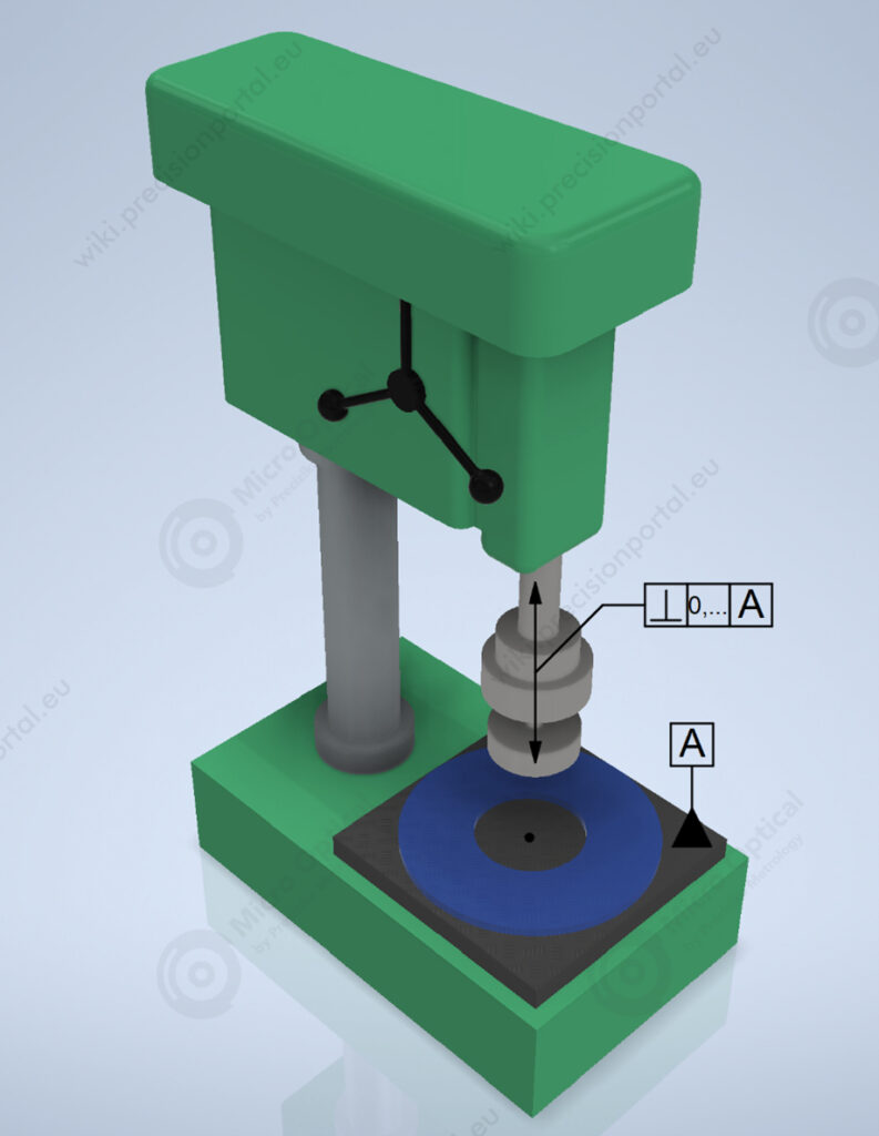
Discs blanks manufacturing process starts by drilling inside hole. Glass blank is fixed on the base A. Drill is aligned with the relation base A and radial beating is measured by the same base. Hole we get is perpendicular to the disc‘s surface.
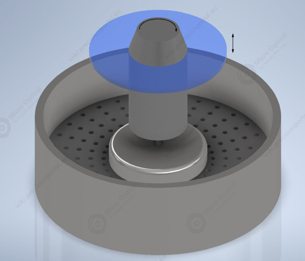
Drilled hole‘s form is corrected on taper, by abrasive powders, when the glass blank is pressed down on on the rotating by clockwise tapper.
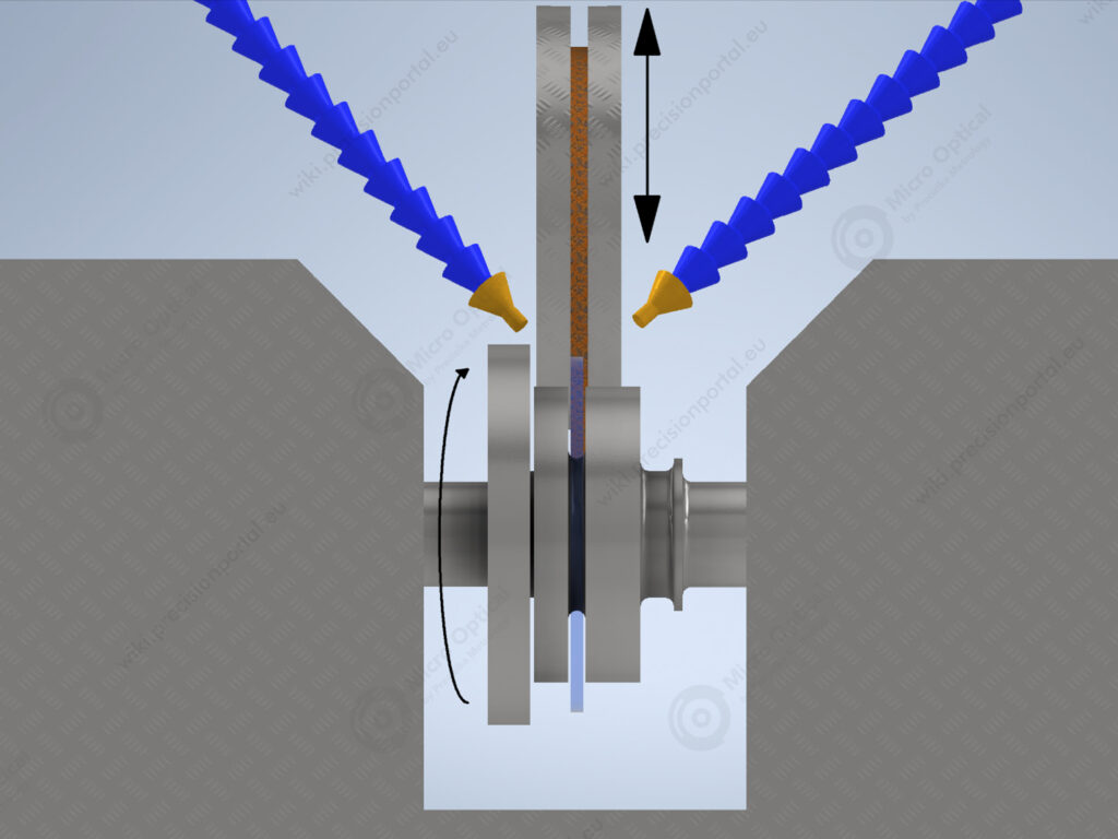
Outside diameter surface is grinding and his axies perpendicular to surface unsures by precision mandrell.
Parallelism
In geometry, parallel lines are lines in a plane which do not meet; that is, two straight lines in a plane that do not intersect at any point are said to be parallel.
The normal form or Surface Parallelism is a tolerance that controls parallelism between two surfaces or features. The surface form is controlled similar to flatness with two parallel planes acting as its tolerance zone.
Two parallel planes or lines which are oriented parallel to the datum feature or surface. All points that are on the referenced feature must in the tolerance zone.
Remember: Parallelism does not directly control the angle of the referenced surface; it controls the envelope (like flatness) where the surface needs to be. The goal is to ensure all points are within a specified tolerance distance away from their corresponding datum points.
(Source: https://www.gdandtbasics.com/parallelism)
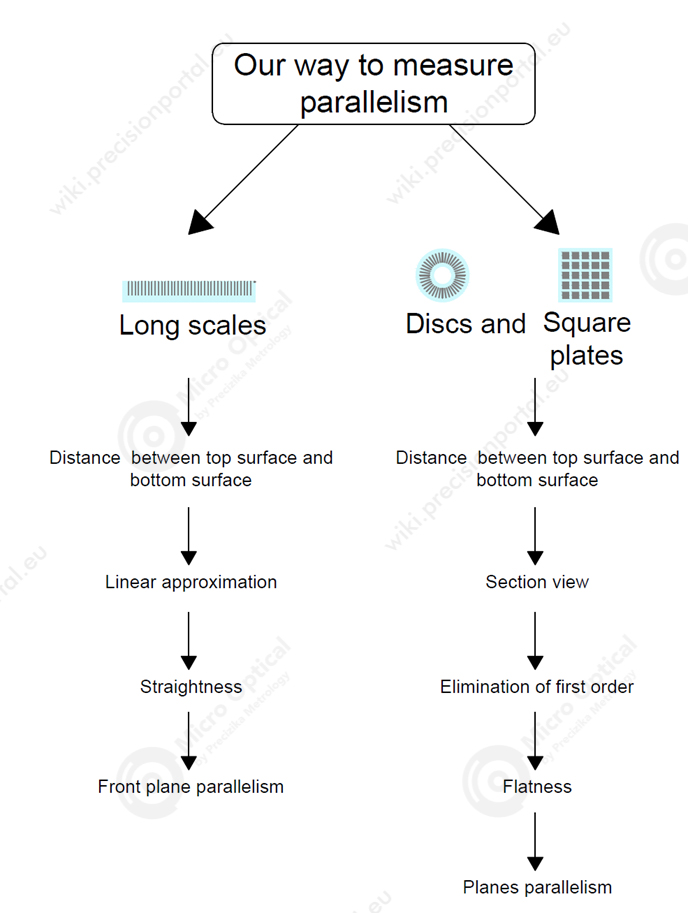
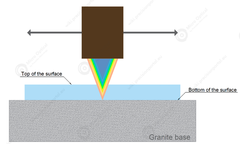
Glass scale blank is placed on smooth granite base surface. Above it, confocal distance sensor measures distance, between blanks top of the surface and bottom of the surface.
Sensor is fixed on the carriage, which moves by air bearings, parallel to granite base. Distances measured in this way, are placed in one line, and shows us blanks surface straightness.
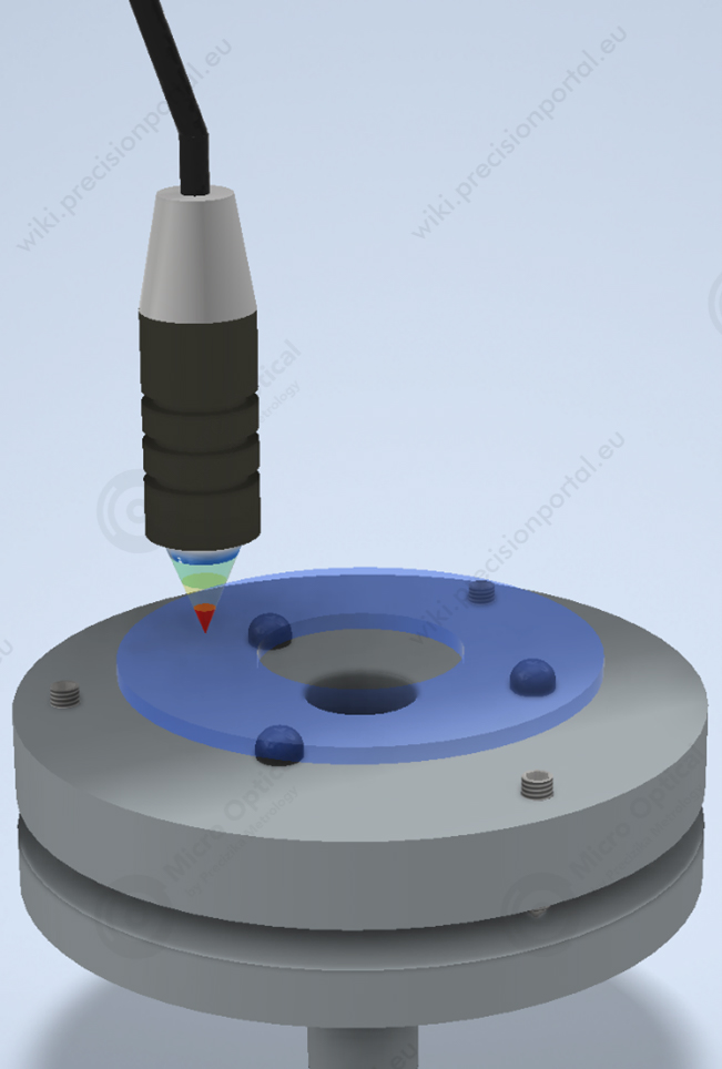
Glass disc blank, is placed on three sphere supports, in alingement table, which is adjustable with three adjustment screws. Table is placed on spindle which rotates by air bearings (confocal distance device is rigidly fixed, but table is rotating). In this way we measure distances between blanks top of the surface and bottom of the surface in circular. From the given results we can calculate flatness. Also, after that we can eliminate 1 harmonic.
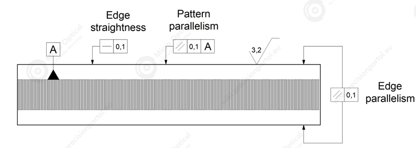
Pattern parallelism
The horizontal elements of the scale pattern must be parallel to the edge (edges) of the scale blank. Most often, the base line is marked on the scale pattern and the parallelism of the edge of the scale is indicated against to it. If the bearings of the reading head roll on the surface of the scale edge, then there are also requirements for the straightness and roughness of the scale edge.
Surface Parallelism
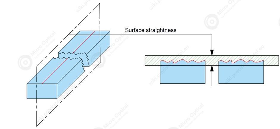
Surface Straightness is a tolerance that controls the form of a line somewhere on the surface or the feature.
The standard form of straightness is a 2-Dimensional tolerance that is used to ensure that a part is uniform across a surface or feature. Straightness can apply to either a flat feature such as the surface of a block, or it can apply to the surface of a cylinder along the axial direction. It is defined as the variance of the surface within a specified line on that surface.
Two Parallel Lines on either side of a surface line where the surface must lie (2D)
Scale’s blank edge straightness – the edge straightness is measured by placing a straight ruler along the straight edges of the glass and measuring the distance between the ruler and the glass, with the glass in vertical position.
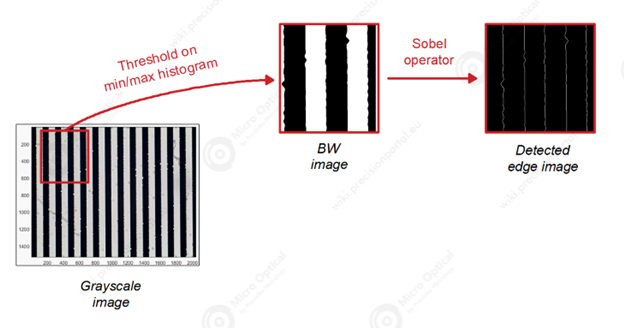
Line Edge Straightness
Roughness
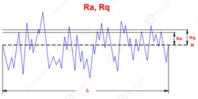
Roughness is a measurement of the small-scale variations in the height of a physical surface. A common measure of surface roughness is the rms (root-mean-square) height of the surface bumps. Part of our refined processes in providing the most excellent encoder glass scales and discs is our advanced glass roughness measuring equipment. With this, we can make sure the glass scale roughness you require is up to spec.
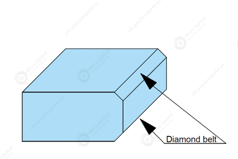
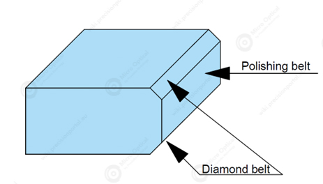
On product, edge we get after few operations. Glass scales cutted to required dimensions with carbide wheels and hand-broken on special table. Further, scale goes through wet different grit size diamonds belts. Depending on glass thickness and linear speed of diamond belts we get required edge roughness. The position of the belt is fixed at a certain angle to the edge.
Disc‘s inside diameter is drilled by diamond drill and final dimension is corrected on tapper with abrasive powders . Abrasive powders size affects mentioned edge roughness. Outside diameter apears by grinding discs grit size and work mode (speed, emulsions, feed and etc.)
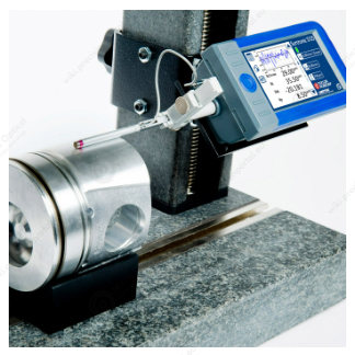
Surface roughness tester
(Source https://topmetrology.ro/en/product/rugozimetru-taylor-hobson-surtronic-s-100/)
Polished float glass has a typical surface roughness of <0.05 micrometer/20 mm, peak-to-peak, for 1.1 mm substrates, and <0.075 micrometer/20 mm, peak-to-peak, for 0.7 mm substrates.
Unpolished float glass has a typical surface roughness of <0.15 micrometer/20 mm, peak-to-peak, for 1.1 mm substrates, and <0.20 micrometer/20 mm, peak-to-peak, for 0.7 mm substrates..
| Material | Ra (nm) | Rz (nm) |
|---|---|---|
| Soda-Lime Glass | 0,73 | 5,4 |
| Borofloat | <1,5 | - |
| BK7 | 0,725 | 5,647 |
| Fused quartz | 0,295 | 2,047 |
| Zerodur | 0,541 | 4,217 |
| Borosilicate glass | 0,707 | 7,181 |
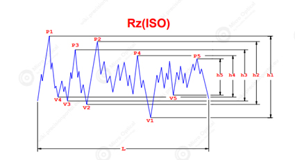
Ten Point Height of Irregularities, Rz(ISO), is the average value of the absolute values of the heights of five highest profile peaks ant the depths of five deepest valleys within the evaluation.
Outside diameter surface is grinding and his axies perpendicular to surface unsures by precision mandrell.
Chamfer (Bevel)
Chamfer (Bevel) – This type of edging involves flat grinding glass edges until they are smooth and then running the top and bottom edges along a belt to eliminate sharpness and remove chips. The resulting glass piece features a smooth chamfer top and bottom with an exterior ground edge.
On our products we do chamfers to increase glass riginity, so that it does not break when blank is deformed.
Chamfer sizes, that we can make are from 100 mikrometres to 500 mikrometres.
Chamfer dimensioning types:
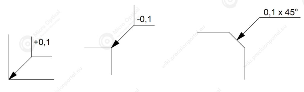
DIN ISO 13715
This type of edging involves flat grinding glass edges until they are smooth and then running the top and bottom edges along a belt to eliminate sharpness and remove chips. The resulting glass piece features a smooth chamfer top and bottom with an exterior ground edge. Available with straight or curved bevels, chamfered edges are most often seen on frameless mirros, such as those on medicine cabinets.
This method cutting edges of the glass and then flat polishing them, resulting in a seek appearance amd shiny or glossy finish. Most flat-polished applications also employ a small 45° angle chamfer on top and bottom glass edge to remove sharpness and “chatter“ which can also be polished.
This method cutting edges of the glass and then flat polishing them, resulting in a seek appearance amd shiny or glossy finish. Most flat-polished applications also employ a small 45° angle chamfer on top and bottom glass edge to remove sharpness and “chatter“ which can also be polished.
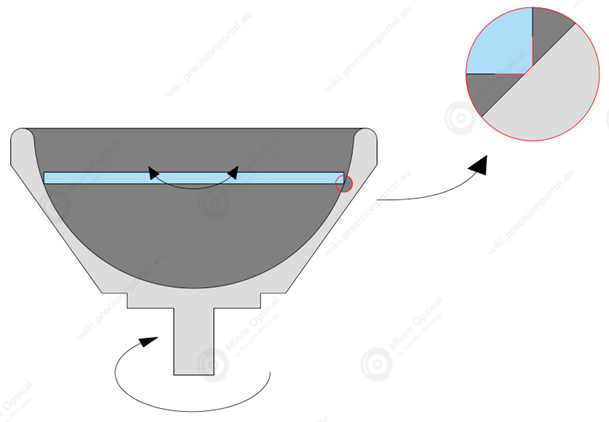
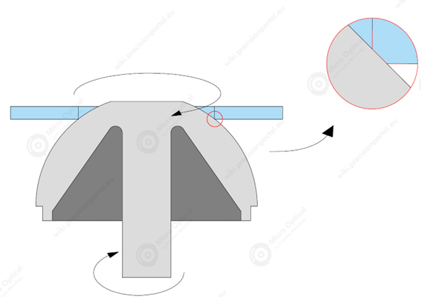
Outside diameter’s chamfer, forms rotating spherical shape’s grinding tool, while glass blank is rotating in the opposite direction. Grinding tool’s surface, before every new blank, is covered by fine abrasive powders. Grinding tool’s radius comply with glass blanks outside diameter. The glass blank is held by hands or with special equipment.
Inside diameter’s chamfer, forms rotating spherical shape’s grinding tool, while glass blank is rotating in the opposite direction. Grinding tool’s surface, before every new blank, is covered by fine abrasive powders. Grinding tool’s radius comply with glass blanks inside diameter. The glass blank is held by hands or with special equipment.
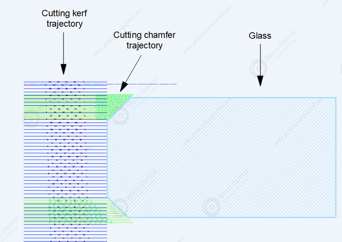
Half of our production chamfers forms laser. Both chamfers, climbs to top and bottom surfaces.
Accuracy
Accuracy is a measure of the error between the value read out by the encoder and the actual physical value being measured. The widths of the lines on the optical encoder disk can vary, for example.
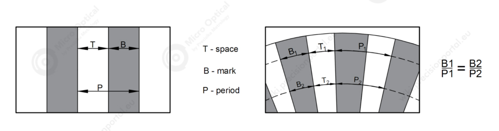
| Mark period ratio | Duty Cycle ratio | Tolerance for line – width | |
|---|---|---|---|
| Formula | B±5% | ||
| Tolerances | 20 µm period 10/20 = 0,5 9/20 = 0,45 MIN 11/20 = 0,55 MAX | 20 µm period 10/10 = 0,5 9,5/10,5 = 0,9 MIN 10,5/9,5 = 1,1 MAX | 10 µm mark 10 – 100% 10 – 100% B – 105% B – 95% B – 10,5 MAX B – 9,5 MIN |
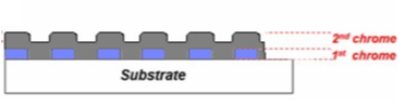
Multi-Layer Pattern
Multi-layer pattern: 1st chrome layer – 800Å, 2nd chrome layer -2000 Å.
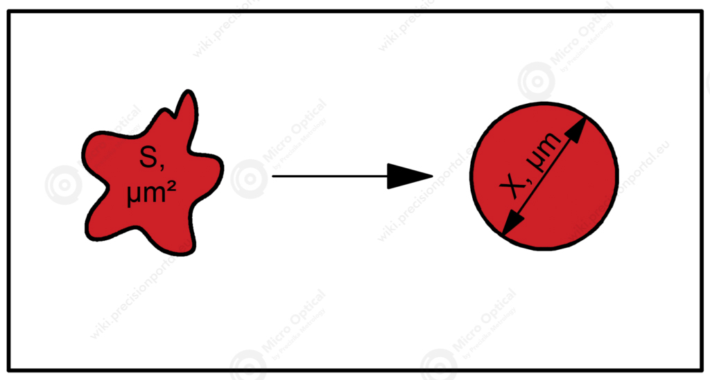
Single Chrome Pattern

Diameter of a circle of equal projection area / EQPC – This is the diameter of a circle that has the same area as the projection area of the particle. It is widely used for the evaluation of particles sizes from the projection area A of a non-spherical particle.

Standardization
Reflective chrome scales ISO Standardization.
In 1985, the ISO adopted the principle of independency.
The ISO defines it as follows:
ISO 8015 “Principle of Independency”
Each specified dimensional or geometric tolerance on a drawing shall be met independently, unless a particular relationship is specified.
- Dimensional tolerances do not control form deviations.
- Form deviations are controlled by geometric tolerances.
- A linear tolerance controls only the actual local sizes (two-point measurements) of a feature.
U.S. Standardization
The American standard organization is ASME, is using the envelope principle. The envelope principle is the concept that the indicated toleranced size also controls the geometrical characteristics if the target is a feature of size. This means that, under the ASME provisions, unlike the ISO, which provides that dimensional and geometric tolerances be separately defined for a feature of size, an indication of dimensional tolerance also doubles as an indication of geometric tolerance.
ASME Y14.5-2009 “Envelope Principle”
The indicated toleranced size also controls the geometrical characteristics for a feature of size.
ASME also adopted the independence symbol in 2009. When not applying the envelope principle, the principle of independency is applied using an original symbol; the ASME is becoming more consistent with the ISO in terms of indication.
Comparison of ISO and ASME
Both the ISO and the ASME are active in their pursuit of standardization, aiming for a globalization of drawings. However, there are still some differences in symbols and notations. Care must be taken when reading and creating drawings.